|
Project to install LC575 Analogboard on Color Classic
Last week the shipping company destroyed the LC575. I changed my mind and decided to collect the garbage parts to make one. When I had a CC that was in a bad state (I couldn't use logic board, analog board and floppy drive), so I decided to make one with my spare parts. I've always liked 68K compact Macs. Most of the parts were sleeping at home. It will be about 25 years long…
The base CC was the worst individual I had. BTW, Is the PIC beautiful? Actually I was thinking of selling it on e-Bay lol, but even if the condition is very very bad, CC is rare computer. The case is a bit missing, but was it dropped by someone? Originally, this was in my home in this state. It's out of the question, but CC was disassembled, washed and bleached after this. It can hardly be reused except for CRT and wiring.
Let's get back on track! The benefits of using the LC575 analog are many. The power inlet and the slot of the main body can be placed in exactly the same position. Fan connector locations also. Although not measured, it can be assumed that the power supply is powerful because of its large power supply capacity (because there are mounted parts such as a CD drive). There are also default stereo outputs for the built-in speakers. *There is a little issue but I’m currently investigating.
*Sorry, This is the pic after cutting.
I'll tell you not to get confused, but since the LC575 logic board is used by connecting it to the LC575 analog board, the environment before the CRT output is exactly the LC575 itself. After that you have to change the CRT output, It should be done in line with the change from a 13-inch to an 11-inch Trinitron CRT. If you do not do it, it will be displayed, but it will not be full screen like the image. As will be described later, this modification requires CC’s original FBT (flyback transformer). And VGA (640X480) output is possible with genuine specifications. Moreover, like the genuine LC575/550/520, the logic board (motherboard) can be replaced without modification (Pin-out mods), and you can boot from any of them. If you replace this with CC, VGA can be started for both CC I and II. I haven't tried it, but I think you can get the same results with the LC550 and LC520 analog boards.
Also, as for me, I am not a professional (not 100% amateur because I have a background as an electric guitar designer) and 100% do not understand the concept of this analog board. Please let me know if the description is incorrect.
To install LC575 analog board
If the CC analog board is broken, you can replace it with the LC575(550/520) analog board for repair with little work. I’m gonna teach you the process. Originally, this analog with genuine VGA output has plenty of power capacity, and it is suitable for converting color classic to PPC or 68040.
important point! : If you get an electric shock from my article or your important ColorClassic breaks, I take no responsibility.
Things necessary: 1, FBT(flyback transformer) 157-0146 will be reused, so it must be usable. And CC Brocken Analog board. 2, LC575 analog board *Use a fully operational product. Maybe needs Re-cap.
Required processing location: 1,PCB cut left and right is 19mm(0.75 inch). 2, Move with a jumper with a pattern that crosses the cut line. 3, Replace few parts from CC analog board. 4, Replace FBT from CC board. 5, Installing the speaker cable from LC575 board. *Stereo possible. 6, Chassis rail processing (cutting) 7, Processing of analog board earth plate and replace connector cover. 8, CRT yoke plate ring and analog pot adjustment
Issues: 1, Stereo output does not sync left and right. 2, The horizontal adjustment area is slightly narrow. Approximately 4 mm (0.16 inches) outside the display screen area. I will talk about this at the end of the sentence.
Working method
1,PCB cut, The hardest work
Cut with 19mm cut lines on both ends. I make a notch on the P-cutter(OLFA 1090486 PC-L Plastic/Laminate Scorer) from both sides of the PCB. At this time, pay attention to the pattern on the right side from the back. Separate it here and reuse it. The two resistors that are exactly on the cut line are transplanted to the side of the main analog board ( ↓see the bellow). Then, when separated, cut the four ends diagonally. The transistor and the potentiometer on the cut line are remove once at this point. *Will reuse later. In particular, make a large diagonal cut so that the part that hits the claws of the chassis does not hit.
2,Jumper handling
Move with a jumper with a pattern that crosses the cut line. Connect the 6 jumper wires to the positions shown in the image. Use the extra holes to thread from front to back. Make sure the jumper wire is in its original position so that you do not make a mistake. At this point try connecting to the LC575 once and see if it works. *If you have the LC575 body
*Separated PCB with double-sided tape.
3, Replace Few parts circuits from the CC board.
I transplanted the parts in this area one by one for confirmation, but as a result, I did not see a big change. So if you are worried, try replacing it! If you just move it, it is not an important task, and when you try it, With or without replacement both parts will work. However, there are differences in the following parts as the circuit to the FBT, so I replaced them in my case.
I’m not even sure about the circuitry on this analog board, but perhaps this blue box is an FBT amplifier. Since the FBT is different, it seems that it needs to be replaced, I believe it is the only incompatible part. Looking at the back side, there are not enough patterns, so add jumper wires using through holes.
The following differences were discovered, but no major change was seen even after replacement:
- firm capacitor, the withstand voltage is the same, but the values were little different when measured. But don’t need to replace it. - CRT back PCB, It seems that they are using the same one, but I changed it considering the cable handling. Since there is a difference between the snap mount and the solder mount, in the case of the snap mount, the snap receiving side is also replaced. - Coils, they seems same parts for me… - Blue disc type capacitor, which is not mounted on CC. No change was seen. I don't care if you have it or not. It may be a kind of smoothing circuit.
|


4, Replace FBT from CC board.

The easiest work, But the big point.. Remove and replace. It is a place where solder is absorbed a lot.
LC575 FBT: 157-0149
CC FBT : 157-0146*Use this.
FBT back side, Focus on this area.

5, Installing the speaker cable from LC575 board.
*Stereo possible, However, in some applications there is a left-right lag in the sound latency.

The connector of the LC575 is a type that is pressed to make contact. Remove it and install the wiring. I had another speaker with stock parts, so I tried stereo wiring. If it is monaural, use only one amplifier.


6, Chassis rail processing (cutting)


Separate the chassis at the rail. It is necessary to make some space for the part that hits the mounting parts.


I made a notch in the PCB and clipped it.

7, Processing of analog board earth plate and replace connector cover.
The earth plate cuts off the part on the board, that is, the claw part. The connector cover was transplanted. Incidentally, the microphone cable is a little long, so I replaced it from CC. Initially the connector cover was cut down, but since CC's can be used, this was also replaced.


8, CRT yoke plate ring and analog pot adjustment
|
*Important: Wear insulated gloves to prevent electric shock. |

In most cases, the adjustment range on the Potentiometors on the analog board will be exceeded, so adjustment on the CRT side is necessary. It is located at the base of the glass neck.
There is a yoke plate ring on the base of the glass neck. This can adjust the tilt and RGB synchronization, but it is quite difficult for anyone to do. Even if it takes 2 hours or more to make adjustments, you have to make some compromises…
When all the work is done…
Install the case back, but be careful as it is not on the rails. Store the AC inlet and the switch while aligning them with the holes on the case side. If you cut the left and right exactly 19 mm, it will fit surely!


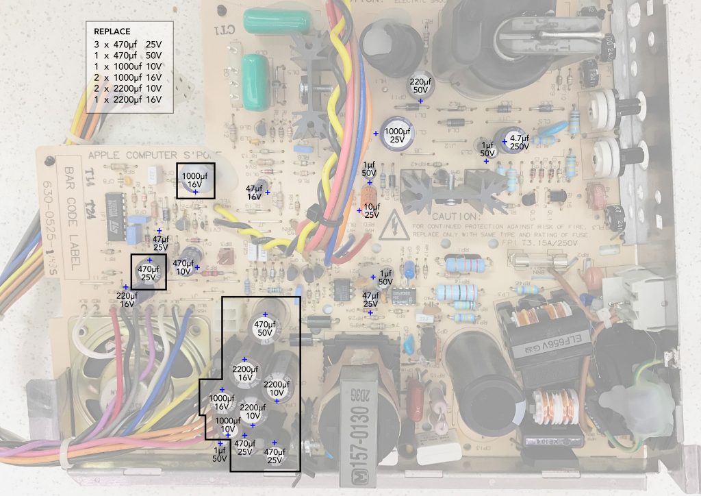
Finally, once the startup is confirmed, replace it without using it for a long time and re-caps. I use an ESR tester to measure the equivalent DC resistance. And since the caps with a large value is deteriorating, I will replace it soon.
Here are some good pages on repair shops.
.
Impressions and challenges after Mods
What I was most interested in was the horizontal display adjustment part. This time, the horizontal deflection voltage was not touched. However, when I tried an experiment to boost the horizontal deflection voltage from 60V to 68.4V like Mystic (See bellow Schematics and TEST 1), the horizontal sync frequency seems to be good and it is possible to adjust it so that it protrudes from the screen. However, when I made this modification, the vertical sync frequency became little lower, and the vertical height adjustment range became narrower.
This schematic is borrowed from the original Doping Mac by Tak Imai and his friends, who is famous CC legendaly guy build first Mystic and Power CC.
Left: Genuine as it is, Right: Voltage up for VGA display

Pin-out

* I didn't try Hi-res mod (Horizontal sync voltage 84V, disconnect 8-pin from GND and connect 8-pin and 10-pin together), Cuz 10-pin out is little different from CC analog board, I'm not sure how much the volt here... And sorry, the LC575 transformer pinout concept is currently incomplete.
It will be completed when the vertical sync voltage can be slightly increased along with the horizontal sync voltage.

Each display result is the image below:


-----------------------------------------------------------------------------
*TEST 1

This Mods seems to run out of vertical sync voltage, narrowing the range of vertical sync adjustment. The maximum screen on the vertical axis is above.
-----------------------------------------------------------------------------
So it's settled down in its original condition. This mod would be a more perfect hack if anyone could approach it with the full concept.
I took the time to do this partly because I wanted to help users who are worried about analog boards. Someone with time Try this mods. And try to make a better result in the display area. If I come up with an idea, I would like to try more. Thank you for reading the long sentence. And thank you for dating my Bad English. I hope it's not the worst…
Regards,
Kay Koba